Good pinball deals still happen.. but become more and more rare.
Checked out a Twilight Zone pinball machine that someone had bought in a local auction house.
At these auctions usually furniture is sold, pinball machines almost never show up.
The owner was lucky to be there at the right time, and got it for a very good price: 300 euro (about $450).
That's a steal..
The game is in reasonably good condition.
Service buttons were gummed up. Cleaned them and they started to register again.
Boards are exceptionally clean, looking almost brand new. No battery damage at all.
I get the impression this game was not on location for a long time, or it was a very clean location (not a bar where people smoke), as the inside was very clean.
Worst thing was that the mini-playfield was faded, above the magnets are red circles and letters, one was still bright red and the other had faded to almost white.
Main playfield looked good, no wear.
The game had some usual issues you encounter with TZ: slot machine plastic broken, target bent back.
Clock has a broken 12o'clock opto. Clock face was white with gold-colored signs.
No 3rd magnet or special signs on the mini playfield. 2 posts under the popbumper were installed.
This means the game is probably a very early production game. It was still on L-2 version roms.
All coils worked, except for 2 that had a broken wire.
Biggest problem was in the switch matrix, 2 rows are shorted to ground. Traced the problem back to the opto driver board under the playfield. The LM339 ic's on this board need to be replaced.
Sometimes I hear about people finding games for a very low price.. it's been a few years now, but this shows you these finds can still happen.
Friday, May 27, 2011
Thursday, May 19, 2011
MM flipper repair
When repairing a pinball machine, always check that genuine pinball parts are used.
I'm restoring a Medieval Madness. When the game came in I played a few games to have an idea how it felt, what parts didn't work well (so I knew I had to pay extra attention to them when I stripped the playfield down).
One of the things that I noticed was that the flippers were really weak. I could barely get a pinball up a ramp. But I assumed the assemblies were just worn and would replace them anyway whilst shopping the game.
I always replace the plunger/link, flipper bushing, coil sleeves and the coil stop.
The coils themselves were still good, the sleeve didn't stick into the coil and could be removed easily.
On this particular game I also replaced on end-of-stroke switch as a part of the long blade was broken and the flipper link would stick behind it, leaving the flipper bat in the up position.
But what this post is about - I noticed something really weird when replacing these parts. The flipper return springs were not pinball parts !

Although they looked similar, they were much larger and thicker than what has to go on there.

Here's an image of the large spring that was installed and the spring that should go on there. The larger spring is too strong, probably they caused the flippers to have not enough power. Had original springs been used the game would have played a lot better. Small things like a 50 cents spring can make or break how well a game plays.

The correct springs I had in my spare toolbox, in which a lot of small spare parts (springs, all types of screws, ..) are laying loose.
When I had installed the new spring and checked its tension, I noticed something was inside the little spring ?! See this picture - it's in the middle of the extended spring.
Quiz time: do you know what was hidden inside the spring ?
And no it's not an airgun pellet (although it looks like it), it is a part used on a pinball machine.
Btw when installing the new flipper return springs and the bushing, I noticed the base plate of the right flipper was of a different type than that of the left flipper.
It was of an older type of WPC pinball, as it didn't have 2 extra holes to mount the little spring in. It was the type of base plate that's used on the older wpc games that had a conical flipper return spring that went around the flipper plunger.
I noticed it was different but didn't think much of this. As I replaced the coilstop and flipper link I thought it wouldn't matter anyway - I should have known better...
When the playfield was totally assembled and I played my first game I noticed my mistake. The right flipper had less travel, whilst they were both aligned to be in the same position when down, in the up position the right flipper didn't come as high as the left flipper.
Big problem.. both flippers really need to act the same whilst playing.
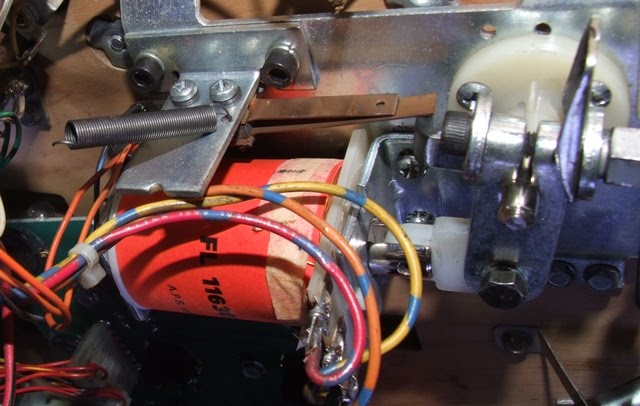
My first thought - as you can see on the first picture was that I had used a generic part for the left flipper. The plastic link is a slightly different shape than on an original Williams part. Thought this maybe had a small size difference with another link which cause the left flipper to raise higher.
As the flipper assembly acts like a lever, a small change in distance of how much the plunger travels (because of a different coil stop for example, or plunger link), will be magnified at the end of the flipper tip.
Removed this whole plunger and link assembly and put a new, correct type in.
No difference, the right flipper still didn't raise as much as the left.
Then I remembered the difference in base plates, and I remembered these were slightly different and you needed to use the correct coil stops on them too (which I didn't have, only have 1 type of generic coil stop in my spare parts).
So I disassembled the whole right flipper again and replaced the base plate with a correct, more recent type.
The differences between both base plates are barely noticeable. Visually they look the same, same size, coilstop and flipper are mounted on the same distance, ..
But they are not the same.
You can identify them: there are less holes in the upright metal where the flipper return spring hooks in, and the flipper bushing is secured with screws that have loose nut on one type, while on the other type the nuts are glued onto the flipper base plate.
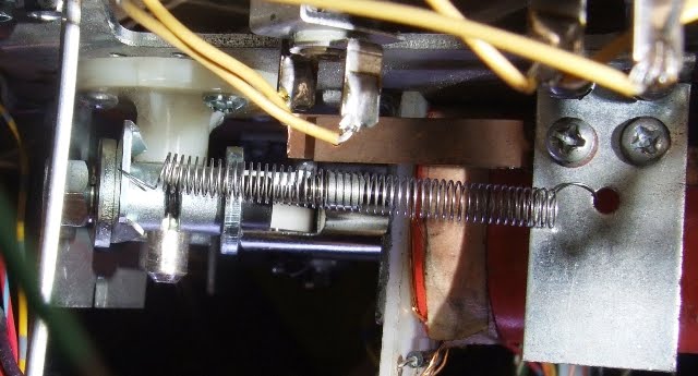
See the difference between the first (good) and third picture (wrong plate) - in the first the spring is stuck in a hole to the side, in the third picture there was no such hole present, it was stuck in a hole in the center.
I'm restoring a Medieval Madness. When the game came in I played a few games to have an idea how it felt, what parts didn't work well (so I knew I had to pay extra attention to them when I stripped the playfield down).
One of the things that I noticed was that the flippers were really weak. I could barely get a pinball up a ramp. But I assumed the assemblies were just worn and would replace them anyway whilst shopping the game.
I always replace the plunger/link, flipper bushing, coil sleeves and the coil stop.
The coils themselves were still good, the sleeve didn't stick into the coil and could be removed easily.
On this particular game I also replaced on end-of-stroke switch as a part of the long blade was broken and the flipper link would stick behind it, leaving the flipper bat in the up position.
But what this post is about - I noticed something really weird when replacing these parts. The flipper return springs were not pinball parts !
Although they looked similar, they were much larger and thicker than what has to go on there.
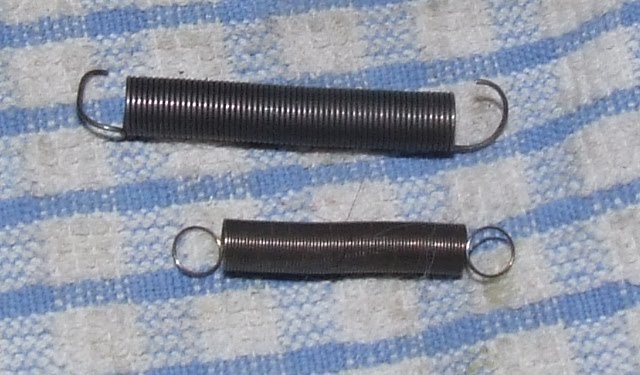
Here's an image of the large spring that was installed and the spring that should go on there. The larger spring is too strong, probably they caused the flippers to have not enough power. Had original springs been used the game would have played a lot better. Small things like a 50 cents spring can make or break how well a game plays.
The correct springs I had in my spare toolbox, in which a lot of small spare parts (springs, all types of screws, ..) are laying loose.
When I had installed the new spring and checked its tension, I noticed something was inside the little spring ?! See this picture - it's in the middle of the extended spring.
Quiz time: do you know what was hidden inside the spring ?
And no it's not an airgun pellet (although it looks like it), it is a part used on a pinball machine.
Btw when installing the new flipper return springs and the bushing, I noticed the base plate of the right flipper was of a different type than that of the left flipper.
It was of an older type of WPC pinball, as it didn't have 2 extra holes to mount the little spring in. It was the type of base plate that's used on the older wpc games that had a conical flipper return spring that went around the flipper plunger.
I noticed it was different but didn't think much of this. As I replaced the coilstop and flipper link I thought it wouldn't matter anyway - I should have known better...
When the playfield was totally assembled and I played my first game I noticed my mistake. The right flipper had less travel, whilst they were both aligned to be in the same position when down, in the up position the right flipper didn't come as high as the left flipper.
Big problem.. both flippers really need to act the same whilst playing.
My first thought - as you can see on the first picture was that I had used a generic part for the left flipper. The plastic link is a slightly different shape than on an original Williams part. Thought this maybe had a small size difference with another link which cause the left flipper to raise higher.
As the flipper assembly acts like a lever, a small change in distance of how much the plunger travels (because of a different coil stop for example, or plunger link), will be magnified at the end of the flipper tip.
Removed this whole plunger and link assembly and put a new, correct type in.
No difference, the right flipper still didn't raise as much as the left.
Then I remembered the difference in base plates, and I remembered these were slightly different and you needed to use the correct coil stops on them too (which I didn't have, only have 1 type of generic coil stop in my spare parts).
So I disassembled the whole right flipper again and replaced the base plate with a correct, more recent type.
The differences between both base plates are barely noticeable. Visually they look the same, same size, coilstop and flipper are mounted on the same distance, ..
But they are not the same.
You can identify them: there are less holes in the upright metal where the flipper return spring hooks in, and the flipper bushing is secured with screws that have loose nut on one type, while on the other type the nuts are glued onto the flipper base plate.
See the difference between the first (good) and third picture (wrong plate) - in the first the spring is stuck in a hole to the side, in the third picture there was no such hole present, it was stuck in a hole in the center.
Sunday, May 15, 2011
Visitors from Finland, it's been busy weekend

We had visitors from Finland over this weekend.
I was contacted a few weeks ago by Teemu, as he was looking to buy pinball machines for sale in Belgium and the Netherlands and wanted some help finding them. Later Ari contacted me too, as he was going to go together with Teemu on this road trip.
This was great news. I had already contact by mail and on irc (#pinball) with Ari about 10 years ago. So I was looking forward to meeting him after all these years.
He's well known in Finland, he's a good player, and has a large website about pinball: apz.fi. (unfortunately almost completely in finnish)
Friday they arrived, we met and we already played some pinball.
Saturday we visited a pinball dealer here in Belgium where we filled their van completely :) Seeing five Medieval Madness pinball machines next to each other was impressive for all of us.
Later Peter from gamebunker.be joined us. The evening was spent in the historic city of Antwerp (you need to do some sightseeing and taste belgian beer), and we even played.. guess what, pinball.
Then we went to some bars in search of a bingo machine.. unfortunately in the first 2 bars we found that had them, all machines were occupied. So we played some Stern Iron Man pinball instead.
Finally we did find a bar with a bingo machine. Ari really wanted to play this type of machine on location..
After having watched people lose over 100 euro whilst we were playing a few games of pinball, we all were curious how well Ari would do.
Well he had been training at home, and said playing pinball had learnt him how to nudge a game skillfully. He put a bit over 2 euro in.. and in the end won 22 euro !
My task was to convince the bar owner to pay us out. After needing to buy another drink he did give us a 20 euro bill. Not bad! Getting 1000% return on your investment isn't bad for 15 minutes of work..
Although it probably won't work every time;. but still, he did much better than some guys we saw losing over 100 euro in those bingo machines..
Maybe this is what pinball needs to become successful again: all the people that are addicted to bingo machines, in the hope to win some money. You're doing it wrong !
Bingo is a gambling game, but your skill can influence it a bit.
First learn to play pinball very well, and use the skills you learnt to earn money on bingo machines.
Sunday we all went to the yearly open air jukebox show in Rosmalen. We visit this show every year.
There were not a lot of pinball machines, even less jukeboxes than previous years. More rock&roll, rockabilly, .. I didn't buy a lot, just a manual for Funhouse and Orbitor One. I'm especially happy with the O1 manual (even it's german) as the game is rare and finding a manual for it is also not easy.. (I only had a bad photocopy of the german manual). Also met some people there that we see every year at the show..
In the afternoon we had to say goodbye as our visitors had to start their long trip back home..
Over the years we've already had some other pinball visitors from abroad at our house (Germany, Poland, Netherlands, United Kingdom), but Ari and Teemu from Finland came from the most far away..
Thursday, May 12, 2011
Medieval Madness troll led modification
Been busy restoring a Medieval Madness the last weeks, it's almost ready.
I'm not crazy about modifications, but wanted to install leds in the eyes of the trolls.
This mod is developed and documented at iobium.com (through their store you can also buy it assembled).
But as I'm more a diy person and the parts only cost a few euros, I decided to do this myself. After all, the kit is very simple: 2 leds, a diode, resistor and some wires (for each troll head), how hard can it be ?
2 days ago I started. Disassembled the trolls, removed the switch and the troll heads. Drilled holes in the eyes.
Soldered 2 leds together like the instructions tell me to do. Put shrinktube around it. Then tried to install it.. and got really frustrated !
It's very difficult to do (maybe the wire I used was a bit too inflexible). You hardly have any space to work, the backside of the trolls face is closed, only at the bottom there's a small hole where the metal of the switch blade sticks through.
Succeeded into putting one led in, tried to get the next in position, first came out again.. repeat repeat repeat and then they decide to break. Aaaaargh.
Out of frustration I quit.
Continued yesterday evening. Can't leave the trolls with holes for eyes, I started it and need to finish this mod.
Took a hobby knife and just cut the backside of the troll open. Put one led in, held it in place with superglue. Waited a few minutes for the glue to cure, got the next led in, glued it also in place. Glued the cut open backside also together.
Victory !
Motivated by the relatively easy installation I started with the second troll head. The frustration of the evening before quickly came back however :-(
Tried to put in one led. It broke. Bending thin metal legs of leds in a 90 degrees angle is not a good idea :(
Soldered a new led on (luckily I have enough leds laying around).
Tested it, it didn't work. Either it was already broken (or broke because of the heat from soldering), or I accidentaly reversed it.
Unsoldered it, put in a new led. (each time soldering a new piece of wire to one of the legs too). Put it in the troll head.. and one leg broke again.
Soldered a new led on. Tested it. Put it in. Success. Glued in place. Let it dry.
Tried to get the second led in place. It broke. AAAAAAAAAAAAAAAAAAAAAAAAAAAAAAArgh !
Pushed hard to get the glued led back out of the head. Soldered a new led and wire to the first. Tested it. Decided to cut the backside of the head open even more.
Finally I was able to put both leds in place and glue everything.
Called it a night.
Tonight I'll continue assembly. Have to solder a resistor and diode and connecting it all to the coil; Shouldn't be too hard to do. Let's hope I don't encounter any surprises.
Anyway, for those interested in this modification: if you don't have many patience or fine motoric skills: just buy the assembled kit !
Sure the parts themselves are cheap if you want to make it yourself, but don't forget to add the price for two hours of your life fiddling in frustration !
And to those persons that like to sell mods like, adding leds into the Medieval Madness dragon, or into the eyes of the martians on Attack from Mars: respect !
You won't see me doing this type of mod, unless when I can just cut something open from behind :-)
Edit: finally finished ! it works great :)
Monday, May 9, 2011
How the switch matrix works
First in a series of tech articles: how the switch matrix works on pinball machines and why those little diodes on switches are imporant.
Thursday, May 5, 2011
TAF repair
Recently repaired a TAF. I actually even had to return as my first repair didn't solve the problem completely. :-(
Issue reported was that sometimes the game gave errors about the bookcase, .. Weird thing is that it didn't happen all the time, only when the game had been played for a while.
Well the problem didn't show up when I was there :( the machine played flawless.
Inspected the boards, another tech had already replaced the connector on the right hand side of the powerboard (J102 if my memory is correct). Maybe to try to resolve the same problem, maybe the game had reset problems in the past. I don't know.
Judging from the condition of the boards, several repairs had already been done to this game.
Measured voltages on the board, everything was ok. Testpoints ok, all leds were on, .. Anyway my guess was that the bookcase error messages were related to the 12v power used for the optos, and for some reason 12v sometimes dropped. Could be on the board or in the wiring.
While checking voltages on the pins going to the playfield, I noticed the connectors at the bottom left of the powerboard were not tight anymore.
There you have J116, J117 and J118. These all provide ground, +5V and +12V to various boards in the game.
One connector especially was very loose. Probably the game had issues with them in the past and that connector must have been unplugged a lot. The metal clips just had lost all their tension and it felt like they did not make a good connection to the header pins.
Checked a few other connectors on the board and they all were in better condition, but not exceptionally good.
Replaced one connector that provided power to the playfield, that's where the optos get their 12v from. Tested the game, still everything worked.. as it was already getting late, and I couldn't reproduce the error, I called it a day.
Instructed the owner of the game that if the issue came back he had to open the backbox and see if all leds were still on (to see if 12v was missing or not on the pcb) and possibly switch J116, J117 and J118 around and see if that solved the problem (the three are interchangeable).
If the problem would come back I could check the rest of the connectors or check out the header pins too. They weren't burnt so I didn't replace them now (usually only GI pins need replacing, not 5v or 12v pins), and I didn't want to remove the powerboard when it was not required as it would further limit the life of the connectors.
A few days later I got an email from the owner, suddenly the dmd display would show garbage.. instructed the owner to reset the grey flatcable. This solved the problem.
A while later I was contacted again. No opto or display problems this time but sometimes the game would just act weird and play completely wrong sounds.
There could be two sources of this problem - either the grey flatcable that connects the cpu to the sound board (the same flatcable also connects the cpu with the fliptronics and dmd driver board). Through the grey flatcable the cpu instructs the soundboard to play specific sound samples. If the data lines have a problem (ie one is blocked) it's possible the game plays the wrong sounds. It was suspect because the garbage on the dmd.
It could also be a problem with the +12 and +5v connectors as some of the boards in the backbox also get their power from these pins, and these definitely were suspect.
Again the problem didn't show itself when I arrived. Swapped connectors on J116, J117 and J118 around and suddenly it did show up. The wrong sample was played, when you would go into the menu you didn't get the typical 'bong' sound but another music. In the selftest the soundboard would play incorrect samples.
With these symptoms you would suspect a grey flatcable, but I got them while playing with the power connectors ? Weird.
Anyway, as these connectors were already suspect I was going to do the repair good.
Didn't have a replacement flatcable with me (later that evening I told the owner where he could order one if the problem would come back). I would start on the powerboard as that was suspect too. Replaced the two other connectors. Removed the powerboard out of the game to replace all the header pins for these three connectors.
With the board out of the game I inspected the backside and I made an interesting discovery. All pins of all connectors had been reflowed ! And I mean ALL of them, even the thin pins for the small flatcable. I have no idea what repair person did this or how long ago it was. It could've been done by the person that replaced the J102 connector, it may have been someone else. I got the impression this Addams Family pinball machine already had a troublesome history.
Finding this made me more suspect about the powerboard and previous repairs. I live by the 'don't fix it if it ain't broken' rule.
Reflowing all pins just shows that someone tried to shotgun a problem, without trying to understand the logic behind it. Else only specific pins related to the issue would've been reflowed. If the game would reset, you only replace or reflow the parts involved. Sound issue ? Same thing. Reflowing everything ? Either the repair person wasn't very skilled, or the issues he was trying to resolve were random and he couldn't reproduce them at all.
It's possible more problems had been introduced by reflowing everything.
I desoldered and removed the header pins for J116, J117 and J118. Installed new pins. Noticed that there was one specific issue with them, one set has one pin connected on the front of the board, while all other traces run along the backside of the board (I believe 5v on J116 to J117, but going from memory here, don't have schematics with me now). Noticed that I had to use enough solder there. When finished I measured continuity between the back of the board and each pin at the front.
On the powerboard there are some pins that have traces on both sides of the board, you have to doublecheck there that you have continuity.
Also measured continuity between the two connectors that are underneath eachother (J117 and J118). But didn't check the trace on the front between J116 and J117.. (only on the backside if the trace had continuity with the pin).
Installed everything again.. now things suddenly got interesting ? :(
The dmd suddenly didn't work at all ? Oops..
Hope I didn't blow up something by accident. No.. just a voltage was missing. (don't remember if it's the 5 or 12v).
Anyway I remembered this one trace on the front. Measured continuity and indeed - it seems one of both pins was not making contact with this trace. Power arrived from the back of the board to one pin, but didn't continue on this pin through the front of the board onto the other two connectors.
Took the powerboard out of the game again, soldered the pins at the frontside of the board to the pcb, measured everything..
Put the board back into the game. Now everything worked correct !
Dmd worked fine, the correct sounds played..
Problem solved and it hasn't come back..
My guess as what the original problem with this board was (before I replaced pins) is that it also had an intermittent contact on one of these connectors. Probably even with the same trace on the front side of the board, as all pins had been reflowed on the backside and that looked good. When the game was off (board was cold) all pins had continuity, but as the machine was played for a while the board and connectors heated up a bit, a pin or the board expanded a bit and broke continuity.
Things I've learned from this repair:
- having a problem with only 5v or 12v on J116/J117/J118 can still make the soundboard work but play incorrect sounds ?!
- always double check and measure continuity in all directions when you've soldered pins.. especially with traces that continue on the front of the pcb!
Subscribe to:
Posts (Atom)
